Material List
Structure
| Label | Member Name | Quantity | Stock Dimension | Length (in) |
|---|---|---|---|---|
| A | Rim Joist | 2 | 2x6 | 238 |
| B | Large Rim Blocks | 2 | 2x4 | 44 |
| C | Medium Rim Blocks | 2 | 2x4 | 38 |
| D | Small Rim Blocks | 8 | 2x4 | 32 |
| E | Large Center Joist | 2 | 2x4 | 44 |
| F | Medium Center Joist | 2 | 2x4 | 38 |
| G | Small Center Joist | 8 | 2x4 | 32 |
| H | Center Rail | 1 | 2x6 | 238 |
| I | Bottom Joist | 14 | 2x4 | 76 |
| J | Mid Rail | 14 | 2x4 | 34 |
| K | Top Rail | 14 | 2x4 | 76 |
| L | Front Post | 28 | 2x4 | 35 |
| M | Large Back Rail | 2 | 2x4 | 44 |
| N | Medium Back Rail | 2 | 2x4 | 38 |
| O | Small Back Rail | 8 | 2x4 | 32 |
| P | Center Post | 14 | 2x4 | 31 |
| Q | Face Board | 14 | 2x8 | 33 |
| R | Large Truss | 2 | 2x4 | 60 |
| S | Small Truss | 2 | 2x4 | 50 |
| T | Large Slats | 12 | 2x6fir | 44.5 |
| U | Medium Slats | 12 | 2x6fir | 38.5 |
| V | Small Slats | 48 | 2x6fir | 32.5 |
| W | Sidewall Hardware Cloth | 7 | 36 | |
| X | Backwall Hardware Cloth | 6 | 36 |
Hardware & Fasteners
| Part Number | Hardware | Quantity | Fasteners | Fastener quantity per unit |
|---|---|---|---|---|
| 1212T | 12" T-strap | 10 | #10 x 2-1/2-in Strong-Drive SD screws | 12 |
| 1212L | 8" L-strap | 60 | #10 x 2-1/2-in Strong-Drive SD screws | 12 |
| A21Z | L-bracket | 48 | #9 x 1-1/2-in Strong-Drive SD screws | 4 |
| L30 | Angle Bracket | 24 | #9 x 1-1/2-in Strong-Drive SD screws | 4 |
| L70 | Angle Bracket | 12 | #9 x 1-1/2-in Strong-Drive SD screws | 8 |
| FB24Z | Hanger Bracket | 28 | #9 x 1-1/2-in Strong-Drive SD screws | 4 |
| Fastener | Quantity |
|---|---|
| #9 x 1-1/2-in Strong-Drive SD screws | 496 |
| #10 x 2-1/2-in Strong-Drive SD screws | 840 |
| #10 polymer coated/exterior screws 2-1/2" | 388 |
Tools
| Tool | Used in |
|---|---|
| 6.5" circular saw (2 batteries) | Step 1 |
| Drill | Steps 2, 3, 5, 6, 8, 9 |
| 1⁄8" drill bit | Steps 2, 3, 6, 8, 9 |
| 3⁄32" drill bit | Step 5 |
| Impact driver | Steps 3, 5, 6, 8, 9 |
| Hex drive bit | Steps 3, 6, 8, 9 |
| Phillips/star/square drive bit | Steps 5, 8 |
| Staple gun | Steps 4, 7 |
| Snips | Steps 4, 7 |
Setup Supplies
- Work table - wood box and 4'x8' plywood sheet
- Saw horses
- Cut jig for lumber
Compost System — Build Instructions
12-bin system · 238" × 84" × 44.5"
Step 1 — Cut all members
Step 2 — Pre-drill
Assembly
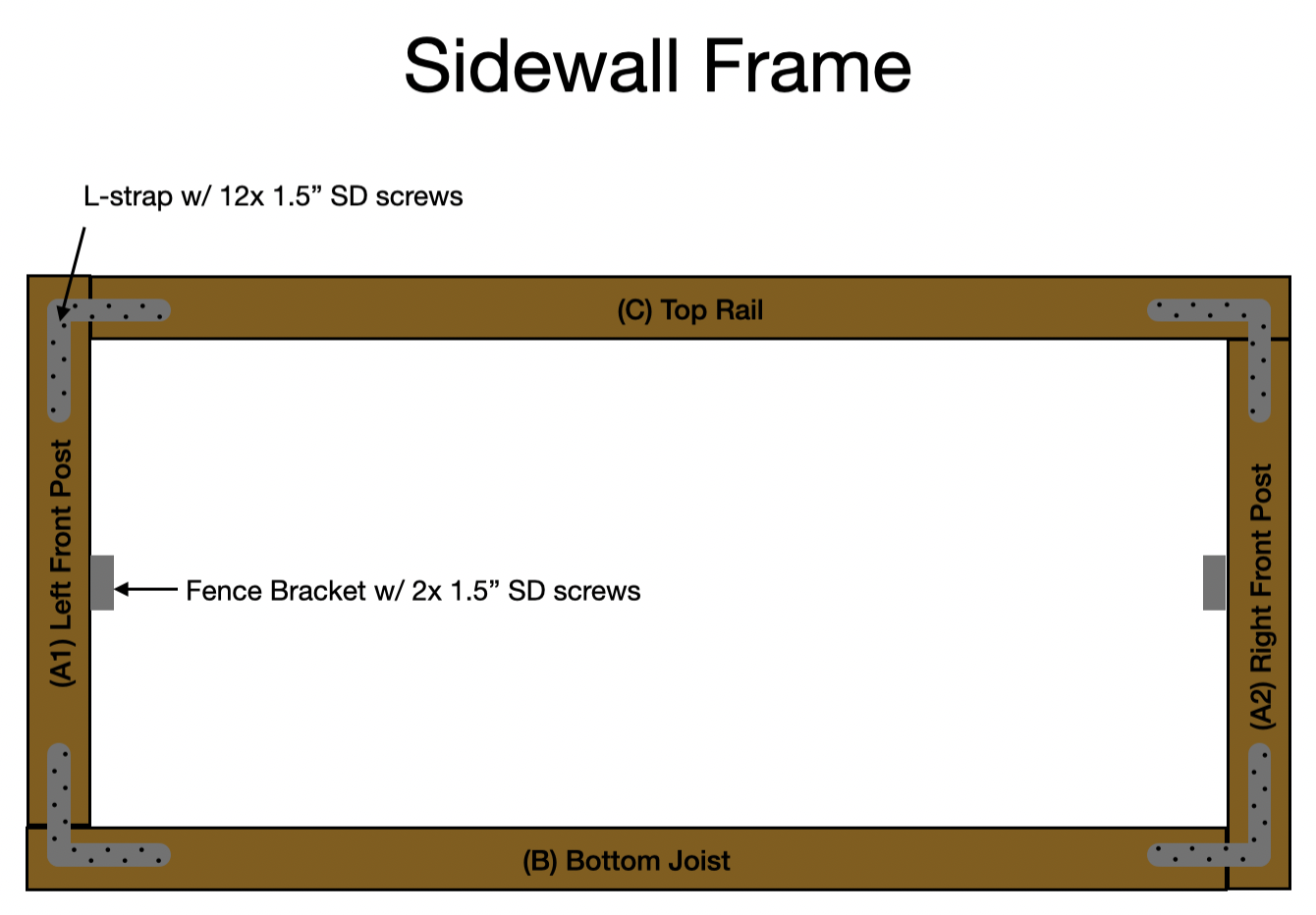
2.1 — Pre-drill Mid Rails (J)
Using a fence bracket as a reference, pre-drill holes in Mid Rails (J) with a 1⁄8" bit.
Step 3 — Assemble Sidewall Frame (one layer)
Repeat 14 times — all layers identical. Rim Joist (A), Face Board (Q), Center Rail (H), Center Post (P), and Mid Rails (J) not included in this step.
Parts (per layer)
| Label | Qty | Member | Size | Length |
|---|---|---|---|---|
| I | 1 | Bottom Joist | 2×4 | 77.5" |
| K | 1 | Top Rail | 2×4 | 77.5" |
| L | 2 | Front Post | 2×4 | 35.5" |
| J | 2 | Mid Rail | 2×4 | 34" |
Tools
| Tools |
|---|
| Drill + 1⁄8" drill bit |
| Impact driver + hex drive bit |
Hardware (per layer)
| Qty | Item |
|---|---|
| 4 | Simpson 8"×8" 14-ga galvanized L-strap |
| 48 | #9 × 1½" Strong-Drive SD screw (12 per strap) |
| 2 | Mid Rail (J) mounting brackets (type TBD) |
Assembly
3.1 — Attach Mid Rail (J) brackets to Front Posts (L)
Stand each Front Post (L) on its narrow edge. Attach one Mid Rail (J) mounting bracket to the inner face of each post. Measure to the bottom of the bracket from the post's bottom end:
| Post | Bottom of bracket from post bottom |
|---|---|
| Left Front Post (L) | 14.25" |
| Right Front Post (L) | 17.75" |
Fasten with #9 × 1½" SD screws.
3.2 — Lay out Bottom Joist (I)
Place Bottom Joist (I) flat, wide face down.
3.3 — Set right Front Post (L)
Wide face down, butt the right Front Post (L) against the right end of the Bottom Joist (I) — bases flush, post does not rest on top of joist.
3.4 — Set left Front Post (L)
Wide face down, place left Front Post (L) on top of the left end of the Bottom Joist (I) — left faces flush.
3.5 — Lay Top Rail (K)
Wide face down, left end butts right face of left Front Post (L), right end rests on top of right Front Post (L).
3.6 — Check for square
- Width (outer face to outer face): 81"
- Height (work surface to top of Top Rail (K)): 39"
- Diagonals equal
3.7 — Fasten L-straps at all four corners
One strap per corner, one leg on Front Post (L), one leg on Top Rail (K) or Bottom Joist (I). Pre-drill and drive 12 × #9 × 1½" SD screws per strap.
Straps face outward when layers are married.
Check before moving on
| Width | 81" |
| Height | 39" |
| Flat — no twist | ✓ |
| 4 L-straps, 48 screws | ✓ |
| 2 Mid Rail (J) brackets at 19.5" | ✓ |
Proceed to Step 4 — Tack and cut hardware cloth onto side wall.
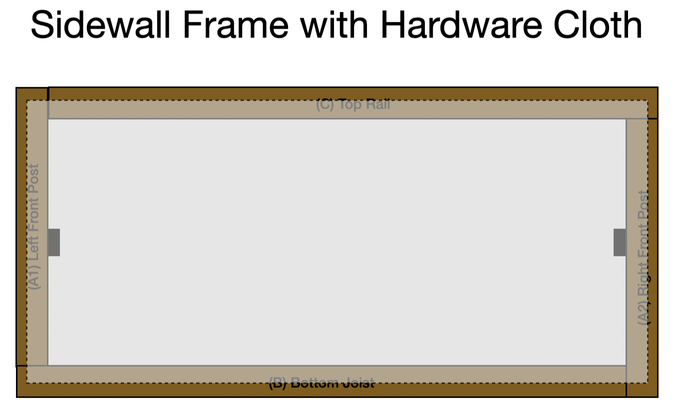
Step 4 — Tack and cut hardware cloth onto side wall
Repeat for 7 of the 14 sidewall frame layers — one per complete sidewall.
Materials
| Materials |
|---|
| Sidewall Hardware Cloth (W) — 3' roll |
| Staples |
Tools
| Tools |
|---|
| Staple gun |
| Snips |
Assembly
4.1 — Position frame
Lay frame flat, L-straps facing down.
4.2 — Roll out Sidewall Hardware Cloth (W)
Starting at one short end of the frame, place the loose end of the roll centered on the frame members. Roll out across the frame keeping cloth taut in both directions.
4.3 — Staple down
Using a staple gun, staple the loose end first, then work across the frame stapling as you go, maintaining tension horizontally and vertically.
4.4 — Cut
Once fully stapled, cut Sidewall Hardware Cloth (W) at the far end so the cut edge lands inside the frame — no exposed edges beyond the lumber.
Step 5 — Marry sidewall assemblies
Repeat 7 times — one per complete sidewall.
Hardware (per sidewall)
| Qty | Item |
|---|---|
| ~48 | #10 × 2½" polymer-coated exterior screws |
Tools
| Tools |
|---|
| Drill + 3⁄32" drill bit |
| Impact driver + phillips/star/square drive bit |
Assembly
5.1 — Lay base layer
Place one frame flat with Sidewall Hardware Cloth (W) facing up.
5.2 — Set top layer
Place second frame on top, L-straps facing up. At each corner, alternate which member overlaps — if the base layer has the Front Post (L) on the outside at a given corner, the top layer should have the Bottom Joist (I) or Top Rail (K) on the outside at that same corner.
5.3 — Align and clamp
Check that outer faces are flush on all four sides before fastening.
5.4 — Pre-drill (outer edge)
Using a 3⁄32" bit, drill through both layers approximately every 24", 1" from the outer edge of each member.
5.5 — Fasten
Drive #10 × 2½" exterior screws into all pre-drilled holes.
5.6 — Flip and fasten inner edge
Flip the assembly over. Pre-drill every 24", 1" from the inner edge of each member, then drive #10 × 2½" exterior screws into all holes. Stagger screw positions so they are not directly in line with those on the opposite side.
Step 6 — Assemble back walls using brackets
6 frames total, 3 sizes — confirm member lengths before starting each one.
Parts (per back wall)
| Label | Qty | Member | Note |
|---|---|---|---|
| P | 2 | Center Post | 2×4 |
| M/N/O | 1 | Back Rail | 2×4 — length varies by bin size |
| E/F/G | 1 | Center Joist | 2×4 — length varies by bin size |
Match Back Rail (M/N/O) and Center Joist (E/F/G) lengths to the correct bin size (large/medium/small) for each assembly.
Hardware (per back wall)
| Qty | Item |
|---|---|
| 4 | A21Z L-bracket |
| 16 | #9 × 1½" Strong-Drive SD screw |
Tools
| Tools |
|---|
| Drill + 1⁄8" drill bit |
| Impact driver + hex driver bit |
Assembly
6.1 — Lay out frame
Lay one Back Rail (M/N/O) flat on the ground. Lay 2 Center Posts (P) on edge at each end of the Back Rail. Lay Center Joist (E/F/G) flat at the bottom of the Center Posts (P) to set the frame.
6.2 — Mark bracket locations
Bring an A21Z L-bracket to each corner. Mark on the Back Rail (M/N/O) and Center Joist (E/F/G) where the bracket edge lands.
6.3 — Drill and fasten brackets
Pre-drill 1⁄8" holes at marked locations on the Back Rail (M/N/O) and Center Joist (E/F/G) at both ends. Fasten each A21Z bracket with 2 × #9 × 1½" Strong-Drive SD screws.
6.4 — Mark Center Posts (P)
Place the Back Rail (M/N/O) and Center Joist (E/F/G) back in line with the Center Posts (P). Mark on each Center Post (P) where the bracket edge lands.
6.5 — Drill Center Posts (P) and complete corners
Using a spare bracket as a drilling guide, pre-drill 1⁄8" holes at the marked locations on the Center Posts (P). Place Center Posts (P) back in position and drive #9 × 1½" SD screws through the bracket already attached to the Back Rail (M/N/O) and Center Joist (E/F/G) into the Center Posts (P).
Step 7 — Tack and cut hardware cloth onto back wall
Repeat for all 6 back wall frame assemblies.
Materials
| Materials |
|---|
| Backwall Hardware Cloth (X) — 3' roll |
| Staples |
Tools
| Tools |
|---|
| Staple gun |
| Snips |
Assembly
7.1 — Tack starting end
Place the loose end of the Backwall Hardware Cloth (X) roll at the midline of one Center Post (P). Staple it in place, keeping the cloth taut vertically.
7.2 — Wrap and tack perimeter
Wrap the roll around the Center Post (P). Working in parallel on the Back Rail (M/N/O) and Center Joist (E/F/G) simultaneously, staple a few inches at a time on each side to keep the roll tracking straight and taut in both directions. Continue around the far Center Post (P) back to the starting post.
7.3 — Cut
Once fully stapled, cut the Backwall Hardware Cloth (X) at the far Center Post (P) — no exposed edges beyond the lumber.
Step 8 — Marry back wall assemblies
Repeat for all 6 back wall frame assemblies.
Parts (per back wall)
| Label | Qty | Member | Note |
|---|---|---|---|
| M/N/O | 1 | Back Rail | 2×4 — match size to assembly |
| E/F/G | 1 | Center Joist | 2×4 — match size to assembly |
Hardware (per back wall)
| Qty | Item |
|---|---|
| 2 | A21Z L-bracket |
| 16 | #9 × 1½" Strong-Drive SD screw |
| 16 | #10 × 2½" polymer-coated exterior screw |
Tools
| Tools |
|---|
| Drill + 1⁄8" drill bit |
| Impact driver + hex driver bit |
| Impact driver + phillips/star/square drive bit |
Assembly
8.1 — Bracket Back Rail (M/N/O) to Center Post (P) (inner side)
Line up the second Back Rail (M/N/O) against the Back Rail with Backwall Hardware Cloth (X) attached, sandwiching the hardware cloth between the two Back Rails. Place an A21Z bracket on the inner side at each end, fastening the Back Rail to the Center Post (P), to draw the members together. Pre-drill 1⁄8" holes and fasten with #9 × 1½" SD screws.
8.2 — Bracket Center Joist (E/F/G) to Center Post (P) (inner side)
Repeat 8.1 for the Center Joist (E/F/G), sandwiching the hardware cloth between the two Center Joists and fastening to the Center Post (P).
8.3 — Fasten second Back Rail (M/N/O)
Pre-drill every 24", roughly 1" from the outer edge of the Back Rail (M/N/O), and fasten the two rails together with #10 × 2½" exterior screws.
8.4 — Fasten second Center Joist (E/F/G)
Repeat 8.3 for the Center Joist (E/F/G).
8.5 — Flip and fasten inner edge
Flip the assembly over. Pre-drill every 24", roughly 1" from the inner edge of the Back Rail (M/N/O) and Center Joist (E/F/G). Fasten with #10 × 2½" exterior screws. Stagger screw positions so they are not directly in line with those on the opposite side.
Step 9 — Stand side walls and back wall, assemble with brackets and attach Rim Joists
Parts
| Label | Qty | Item |
|---|---|---|
| — | 7 | Sidewall assemblies |
| — | 6 | Back wall assemblies |
| A | 2 | Rim Joist |
| B/C/D | 12 | Rim Blocks (1 per bin — match bin size) |
Hardware
| Qty | Item |
|---|---|
| 24 | L30 bracket |
| 96 | #9 × 1½" Strong-Drive SD screw (4 per bracket) |
Tools
| Tools |
|---|
| Drill + 1⁄8" drill bit |
| Impact driver + hex driver bit |
Assembly
9.1 — Mark centerline on sidewall assemblies
On each sidewall assembly, measure and mark the centerline on the Top Rail (K) and Bottom Joist (I) — 40.5" from the outer face of the Front Post (L). This mark will be used to align the back wall.
9.2 — Attach L30 brackets at centerline
On each sidewall assembly, line up 4 L30 brackets along the centerline mark, oriented vertically with the free edge standing up against the centerline. Pre-drill 1⁄8" holes and fasten each bracket with 4 × #9 SD screws. Bracket placement by sidewall:
- 4 interior sidewalls: both sides
- 2 end sidewalls: inside face only
9.3 — Lay out Rim Joists (A)
Lay the Rim Joists (A) flat and parallel on the ground, approximately 7 ft apart.
9.4 — Position first sidewall
Stand one sidewall assembly vertically, perpendicular to and inside the Rim Joists (A).
9.5 — Position back wall
Stand one back wall assembly vertically, aligning the junction of the Center Posts (P) with the Back Rail (M/N/O) and Center Joist (E/F/G) to the centerline marks made in 9.1.